DIY Meshtastic Base Node (ESP32-S3 + LoRa + Solar + BME680) V1.0
A solar-powered, always-on Meshtastic base station with environmental telemetry | ESP32-S3, DX-LR30 (SX1262), and a bare BME680 that fought me the whole way.
Before reading this post: This article assumes a basic understanding of Meshtastic, Meshtastic Nodes, and the Meshtastic Protocol.
Overview
Where the mobile node was about going as low-power and compact as possible, this one is the opposite job: an always-on home base station that sits up high, relays the mesh 24/7, and reports environmental telemetry while it’s at it. It runs on an ESP32-S3, a DX-LR30 (SX1262) LoRa radio, and a BME680 for temperature, humidity, pressure, and air quality; all of it powered off solar so it never needs me to think about it.
The radio side came up fast. Everything else: the web UI, the RAM, and especially that “$5 eBay BME680 sensor,” is where the actual project was.
Parts
All Versions
- ESP32-S3-N16R8 microcontroller
- DX-LR30 LoRa Module (SX1262, ~906.875 MHz, US LongFast)
- BME680 environmental sensor (temp / humidity / pressure / gas + VOC.) The bare eBay module was ~$5.
- 2x 4.7 kΩ resistors (external I2C pull-ups for SDA and SCL. The bare BME680 module doesn’t have them)
- Bulkhead-mounted external antenna
- Solar power chain: 10W panel —> ~30A PWM charge controller —> 12V AGM battery —> Mini360 (MP2307) buck converter
V0.1
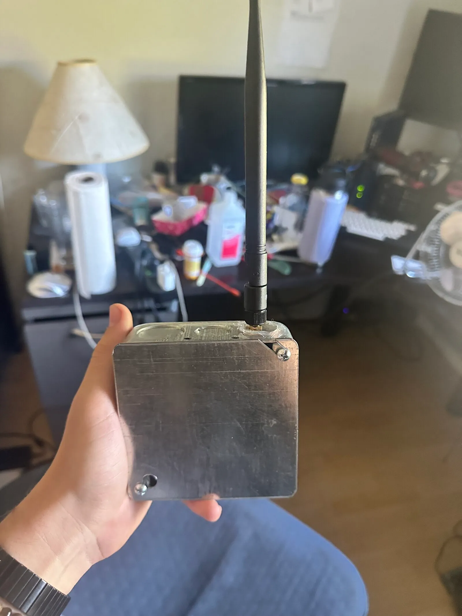
- Metal junction-box enclosure, weatherproofed with RTV
V0.2
- Gefen VGA to DVI Scaler Plus (All internals removed, just used as a chassis), weatherproofed with RTV
Base Node V0.1
How it works
The whole design is built around one clean, shared 3.3V rail. Every part on this node: the ESP32-S3, the DX-LR30, the BME680, and the I2C pull-up resistors, all sit at 3.3V, so there are no logic-level mismatches anywhere on the board to chase down later. That single decision quietly kills off a whole category of subtle bus bugs before they can happen.
Power comes from solar and steps down in stages:
10W panel --> PWM controller (sealed/AGM profile) --> 12V AGM Battery
  --> Mini360 (MP2307) buck, locked at 3.3V --> shared 3.3V rail
       ├── ESP32-S3 (3.3V pin)
       ├── DX-LR30 (SX1262 radio)
       ├── BME680 (kept at 3.3V on purpose. NOT 5V)
       └── 4.7 kΩ I2C pull-ups (to 3.3V)
The ESP32-S3 runs Meshtastic and relays LoRa traffic like any other node. The BME680 hangs off the I2C bus and feeds environmental telemetry into the mesh, so the node isn’t just repeating packets, it’s contributing sensor data my friends and I can actually see. For management I connect over the local network rather than an on-device web server (more on why in a second).
One deliberate note on the BME680 voltage: the eBay listing advertises a “5V supply,” but that just means the little onboard regulator tolerates up to 5V. The chip itself is a 3.3V part, and I keep it at 3.3V on purpose so it never tries to drive the ESP32-S3’s 3.3V-only GPIO toward 5V. Free way to not fry a pin.
What broke / what I learned
Three separate sagas here, roughly in the order they hit me.
The on-device web UI dead end
The plan was to use Meshtastic’s on-device web server for management. WiFi connected, the SSL cert was in place, but the HTTPS server just never started. Digging into the boot log, the LittleFS /static/ directory contained exactly one thing: an empty /static/.gitkeep placeholder. There were no web UI files on the device to actually serve.
Rather than fight the on-device server and the self-signed-cert hassle on a resource-constrained board, I ran the Meshtastic web client locally instead (built from source, pnpm run dev, served at localhost:5173) and connected to the node over plain HTTP at its LAN IP. Sidestepped the whole problem, and honestly it’s the better path for a custom build like this anyway.
Running out of RAM (the heap, not the PSRAM)
The node kept dropping its app connection under load. My first instinct was that I’d run out of memory, and I had, just not the memory I assumed.
This board is an ESP32-S3 N16R8, so it’s got 8MB of PSRAM, and the custom board definitely had it enabled (psram: opi, -DBOARD_HAS_PSRAM). So “out of memory” seemed impossible at first. The thing I didn’t clock right away is that the S3 has two separate pools: ~512KB of fast internal SRAM, and the 8MB of external PSRAM. And they don’t cover for each other; a lot of the hot-path stuff (the WiFi/network stack buffers, plenty of Meshtastic’s runtime allocations) has to live in internal SRAM specifically. PSRAM sitting there mostly empty doesn’t help if the thing that’s full is the internal heap.
And that’s exactly what was happening. My node DB had grown to ~300-320 nodes off a busy mesh, and that was eating internal heap until there wasn’t enough left to keep up. Under heavy traffic the packet queue would back up, the log throws tophone queue is full, discard oldest, and the app connection got dropped when the node couldn’t keep pace.
The fix was to trim the node DB (device.node_db_size) through the Python CLI, which freed enough internal heap to stabilize the link. Worth being precise about why that worked, because it’s easy to misread: trimming the DB didn’t free up PSRAM (there was plenty), it freed up internal SRAM, which is the pool that was actually starved. The 8MB of PSRAM was never the constraint, the 512KB of internal heap was.
That distinction is the whole lesson here. “ESP32-S3 with 8MB PSRAM” makes it sound like you’ll never run out of RAM, but the internal SRAM is a completely separate and much smaller budget, and it’s the one a bloated node DB actually pressures. Not glamorous, but it’s the kind of thing you only really understand once you’ve watched a board with 8MB of “free” memory fall over anyway.
The BME680 that “didn’t work” (it did)
This one was the multi-session epic, and the lesson underneath it is the most useful thing in this whole post.
The BME680 was a bare ~$5 eBay module with no onboard pull-up resistors, which is exactly why it never showed up on the first I2C scan: No I2C devices found. Working through it:
- Missing pull-ups. Bare I2C modules need external pull-ups, so I added 4.7 kΩ from SDA and SCL up to 3.3V (anything from ~2.2 k to 10 k works fine at short wire lengths). The bus came alive.
- Wiring and address. SDA on GPIO 8, SCL on GPIO 9, device at address 0x76 (SDO tied to GND).
- The CS quirk. The generic rule is “CS high = I2C mode,” but this particular module works perfectly with CS tied to GND, proven empirically on my bench, so I left it. Your working wiring log beats the datasheet’s general rule.
- The real culprit: soldering. After a detour through Wago connectors, a shorted 3.3V rail, a battery that died and came back, and a fight with a cheap iron and lead-free solder, what finally fixed it was just a full solder makeover of the joints. The log then read
Register value from 0x76: 0x61, and0x61is the genuine BME680 chip ID, followed byBME680 foundandEnvironment Telemetry: init.
The sensor was never fried. It just had bad joints the entire time, masquerading as a dead chip and a firmware bug across multiple sessions. Prove the hardware in isolation and trust your working wiring log, those two habits would’ve saved me the most time on this build.
Firmware
The Meshtastic side is mostly config flags plus the I2C setup:
- Enable
HAS_I2CandHAS_BME680 - BME680 on I2C: SDA = GPIO 8, SCL = GPIO 9, address 0x76
- External 4.7 kΩ pull-ups on SDA and SCL to 3.3V (hardware, but the bus won’t work without them)
- Node DB trimmed via the Python CLI (
device.node_db_size 100) to survive the no-PSRAM heap limit - Management via the locally-run Meshtastic web client over HTTP, not the on-device HTTPS server
A consolidation trick for the enclosure: solder the two pull-up resistors directly onto the BME680 module (VCC->SDA, VCC->SCL) and jumper CS and SDO on the board itself, so only four wires, 3.3V, GND, SDA, and SCL ever leave the sensor. Cleaner to seal into a weatherproof box.
The firmware will be made available here on my GitHub if anyone is interested.
Result
The node is fully working, on the mesh, relaying traffic, reporting BME680 environmental telemetry, and running entirely on solar. It’s the always-on counterpart to the mobile node: one drives around in the Audi, this one sits up high and holds the fort.
Sanity check I’d recommend to anyone doing this before sealing the box: boot the whole thing on the battery and Mini360 (off USB) and confirm the BME680 still enumerates at 0x76 under real load. Don’t find out it only worked on USB power after the RTV cures.
Photo of working node
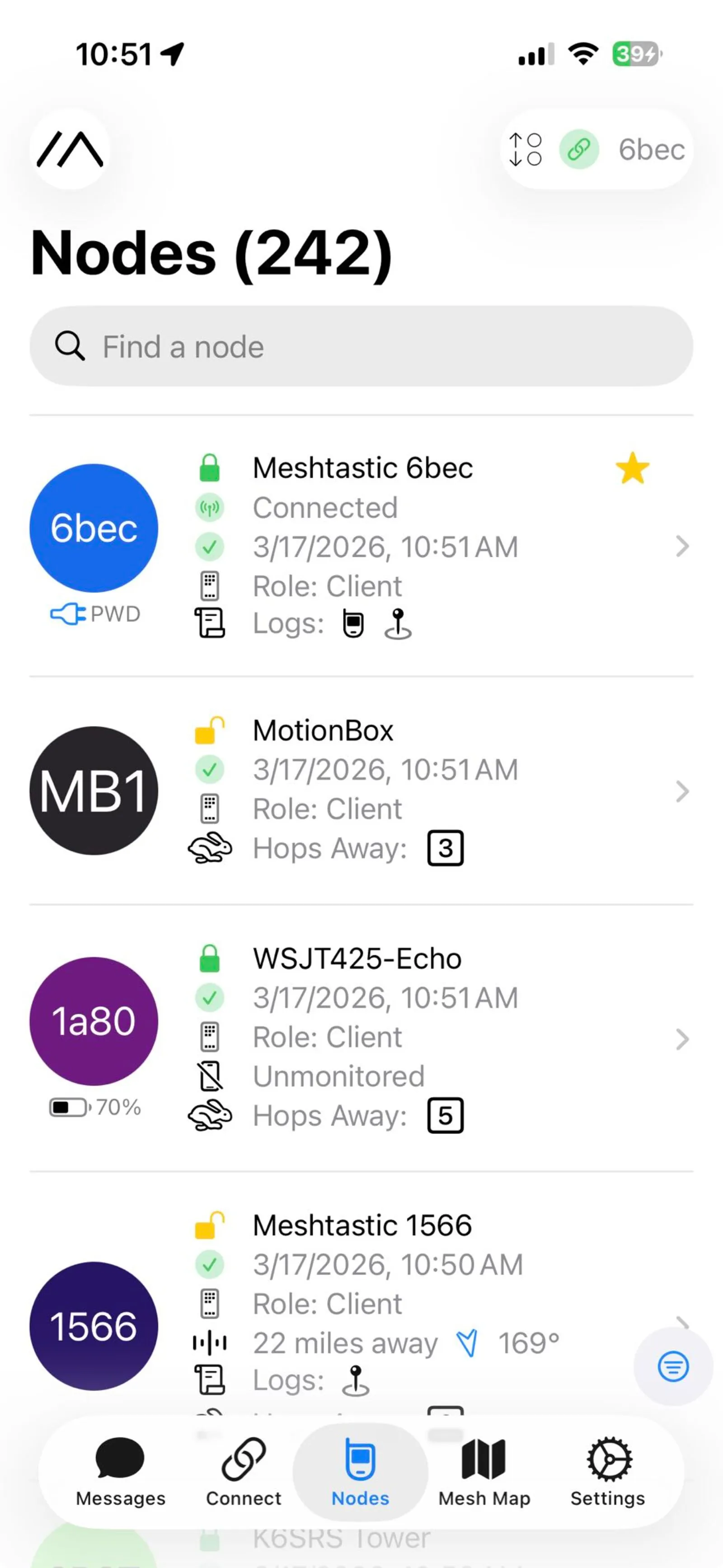 As you can see I was able to catch 242 nodes after letting it run for ~45 minutes.
What’s next
The node relays LoRa fine 24/7, but there’s a catch in my setup: the house WiFi is cycled on and off day/night, so MQTT uplink and remote app access drop for part of every day. The node reconnects on its own when WiFi comes back, but I want continuous capture regardless of the WiFi.
The plan is to use the always-on Raspberry Pi 4B (8GB) as a logger:
- USB serial (preferred): connect the node to the Pi over USB and capture the stream over serial, fully bypassing the flaky WiFi and simplifying indoor power.
- WiFi/TCP (alternative): cleaner cabling, but it inherits possible WiFi outage.
From there: start with the Meshtastic Python CLI --listen logging, then build up to a local Mosquitto MQTT broker —> logger —> SQLite/InfluxDB —> Grafana dashboards for mesh traffic and BME680 history over time. Later and optional: a proper outdoor weatherproof relocation now that the electronics are proven.